
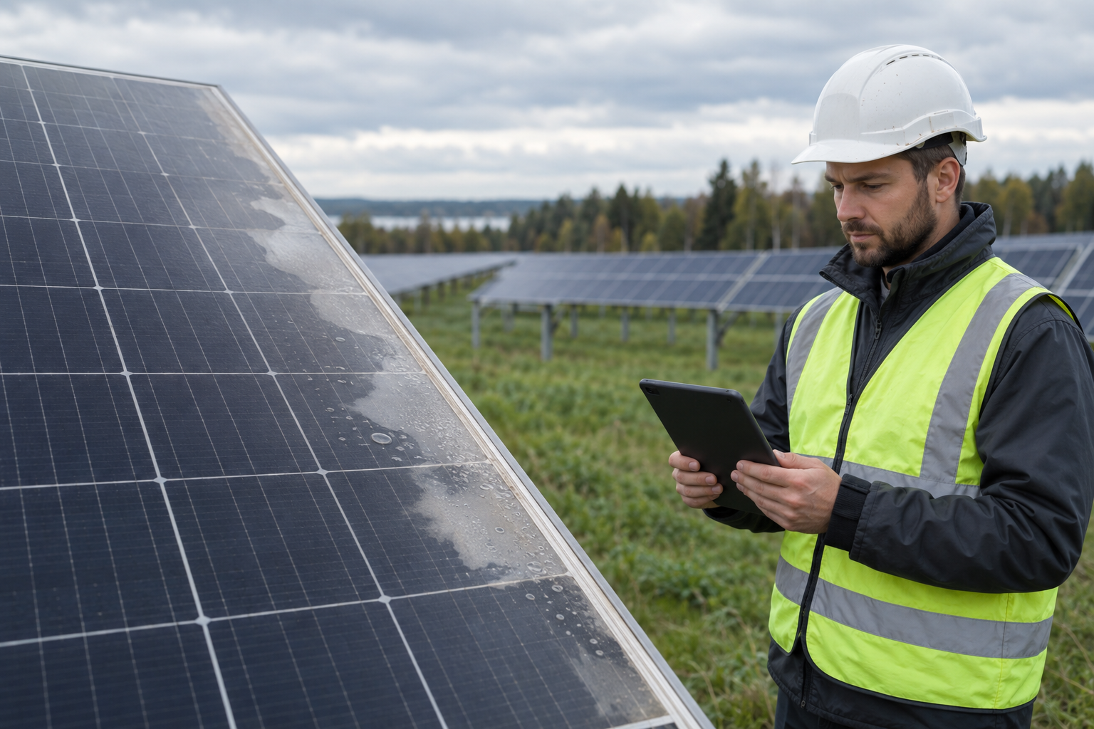

Panel delamination: signs, risks and action at a solar farm
Panel delamination is the separation of a module’s layers, which can allow moisture ingress and lead to electrical faults. Learn how to distinguish it from surface soiling, assess the risks and plan further action.
What is panel delamination and why does it occur?
Panel delamination is the separation of the bonded layers of material within a solar module. It can occur, for example, between the front glass and the cell encapsulant, or within the layers at the rear of the module. Unlike surface soiling, it is a structural defect in the module that cannot be remedied by cleaning.
Layer adhesion can be affected by manufacturing process deficiencies, material ageing, ultraviolet radiation, moisture and repeated temperature fluctuations. Mechanical loads and damage can contribute to the development of the defect, but the specific cause cannot be reliably determined through visual inspection alone.
How can layer separation be distinguished from surface soiling?
Bubbles, milky patches, uneven optical patterns or visible layer separation at the module edges may indicate delamination. These signs should be assessed from different viewing angles, as reflections from the glass and surface deposits can create a similar appearance. Discolouration of the encapsulant alone does not confirm delamination either.
Dust and pollen on panels sit on the external surface, whereas signs of delamination are within the module structure. If the module is not visibly damaged and cleaning is permitted, gently cleaning the surface in accordance with the manufacturer’s instructions can help clarify the observation. The suspect area must not be scratched, pressed or opened.
What risks should be assessed before continued operation?
Layer separation can alter light transmission and allow moisture to enter the module. Depending on the location and progression of the defect, contact corrosion, deterioration of insulation properties and electrical faults may occur. The size of the visible area alone is not sufficient to assess safety or remaining service life.
An urgent inspection by a qualified specialist is required if cracked glass, a damaged backsheet, burn marks or insulation fault alerts are also identified. Any decision to disconnect the affected circuit must be made in accordance with safety procedures. Modules generate voltage when exposed to light even if the inverter is switched off, so disconnecting connectors yourself is not a safe inspection method.
How should a suspect module be inspected?
Start the inspection by recording the module’s identification details and location, and taking overview and detailed photographs. During repeat inspections, aim to maintain similar photographic conditions so that the boundaries of the defect can be compared. If the same signs occur in modules from a single batch, it is advisable to expand the inspection sample.
Insulation resistance measurements help assess the condition of the electrical insulation, but a normal result does not rule out delamination. Measurements must be carried out by qualified personnel using suitable equipment and in accordance with system and manufacturer requirements. Thermography can reveal associated temperature anomalies, but cannot confirm layer separation on its own.
A solar farm’s SCADA system provides operating data that can be used to check for power deviations or fault alerts in the suspect part of the system. These data provide supplementary information: a minor defect may not yet be reflected in overall generation, and normal output is not proof that a module is safe.
Monitoring, replacement and ongoing maintenance
Further action is determined by the technical inspection results, the progression of the defect and the manufacturer’s instructions. If no immediate safety risk is identified, a documented monitoring plan can be established with a scheduled repeat inspection and clear replacement criteria. If insulation deteriorates, corrosion develops or other hazardous damage appears, prompt action is required.
Unauthorised taping of the edges, application of silicone or heating of the module will not restore the original lamination and may hinder further assessment. Any repair approach must be agreed with the manufacturer before work begins; when replacing a damaged module, the electrical and mechanical compatibility of the replacement must also be assessed.
pvcare.eu can help organise defect inspections, documentation and ongoing maintenance in accordance with LVS EN IEC 62446-2:2020. Where necessary, the assessment can be supplemented by a thermal drone inspection with a report on the dronepv.eu website and regular monitoring under an O&M contract.